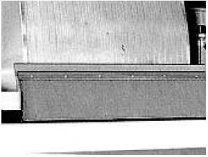
Rotary vacuum filter
The rotary vacuum filter is designed to clarify highly charged liquids, such as white must must and wine lees. It works by continuously scraping the filter layer attached to a rotating drum that is partially immersed in the tank containing the liquid to be filtered.
The liquid to be filtered is drawn through the adjuvant layer on the drum, forming a filter cake that is then scraped to remove the retained particles. Precise adjustment of rotation speed, vacuum level and knife feed are essential to optimise filtration and minimise losses.
The liquid to be filtered is drawn through the adjuvant layer on the drum, forming a filter cake that is then scraped to remove the retained particles. Precise adjustment of rotation speed, vacuum level and knife feed are essential to optimise filtration and minimise losses.
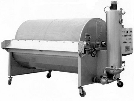
Rotary vacuum filter
This equipment is designed for the clarification of highly charged liquids: white must lees, wine lees, early wines, press wines. The operating principle is the complete opposite of that of filtration using continuous alluvial filters: the initial filter layer is scraped continuously, so clogging is non-existent and the hourly flow rate is virtually constant throughout the filtration process.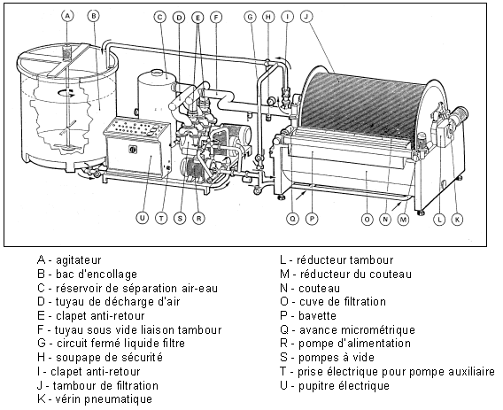
Diagram of a rotary vacuum filter
Main components
Vacuum
This is produced by 1 or 2 "liquid ring" pumps which ensure a constant vacuum inside the drum. The vacuum created sucks the liquid through the layer of additive.The drum
The drum is cylindrical and covered with a stainless steel reps mesh filter cloth. It rotates at an adjustable speed around its horizontal axis. It is partially immersed in a trough fitted with an agitator.- Sector drums: The drum is divided into sectors that do not communicate with each other. The filtrate is evacuated using the vacuum pump to an independent collector which separates the air from the liquid.
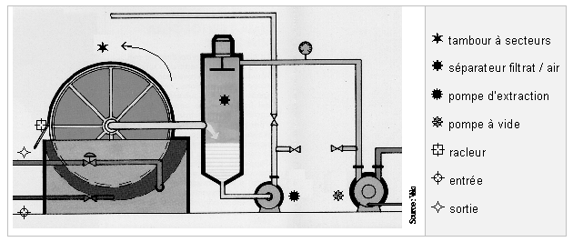
Diagram of a rotary sector vacuum filter
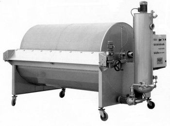
Rotary sector vacuum filter
- Full vacuum drum : The drum is not divided, it is completely evacuated. The filtrate is transferred directly to the storage tank by means of an extraction pump immersed in the lower part of the drum.
In this case, there is a separation between evacuation of the drum and extraction of the filtered liquid (limited oxidation).
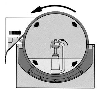
Diagram of a rotary vacuum drum filter
The sizing tank
This is fitted with a stirrer to ensure that the water/additive mixture is homogeneous.Its volume should be proportional to the surface area of the filter.
The control panel
It manages the following settings, among others:- Drum rotation speed
- Knife advance
- Vacuum level
Cake formation
After filling the sizing tank with water, the filtration aid (perlite or diatomaceous earth) is added.To ensure perfect hydration and a homogeneous mixture :
- the quantity of filter aid should not exceed 5% of the total volume of the tank,
- It is important to agitate the water-adjuvant mixture for the time recommended by the manufacturer before transferring it to the filtration trough.
To obtain a stable filter layer, it is necessary to :
- maintain an optimum liquid level in the trough,
- maintain optimum drum rotation speed,
- limit the drying out of the filterlayer at the end of the process.
Indicative maximum values
- perlite: 20 kg/m²
- diatomaceous earth: 30 kg/m²
Note: once the additive has been completely deposited on the drum, it is important to level the whole area using the scraper, in order to eliminate any imperfections in the filter cake.
Filtration control
The liquid to be filtered is fed into the filtration trough by the feed pump.Under the action of the vacuum, the liquid to be filtered passes through the filter cake. The particles to be retained are stopped at the surface of the cake, forming a more or less fine film . After drying, this film is removed by the scraper blade. Its purpose is to continuously remove the undesirable products deposited, as well as a tiny part of the additive layer. This regeneration of the filter medium limits clogging.
Note : deep pollution of the filter cake leads to a reduction in flow rate. To remedy this, the feed rate of the scraper can be increased.
The following diagram shows that the surface of the drum during operation is divided into four different zones:
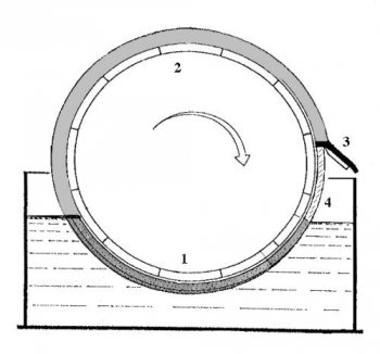
Different zones on the filtration drum
- filtration zone equal to the surface of the submerged part
- drying zone (approximately 2/3 of the total surface area)
- scraping zone
- regenerated sizing zone ready for immersion
Filtration parameters
Vacuum level
This can vary from -0.2 to -0.8 bar (approximately -200 to -800 mm Hg).Rotary vacuum filters operate at a more or less constant differential pressure. In the specific case of musts, this is maintained at around -0.4 bar.
Drum immersion
This can vary between 20 and 50% of the total surface area. Increasing the level of immersion increases the actual filtration surface but reduces the surface area for drying residues.Drum rotation speed
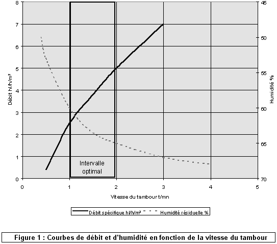
Drum rotation speed can vary from 0.2 to 5 rpm.Increasing the speed of rotation increases the specific flow rate of the product to be filtered and, at the same time, increases residual moisture and wine losses, as the drying phase is reduced.
The graph below shows the optimum range of rotation speeds : this is the compromise between an acceptable specific flow rate and sufficient drying.
Level of scraping
The aim is to remove the clogged layer with a minimum of filter media.The knife feed rate can vary from 1 to around 30 mm per hour.
Optimising the scraping level means ensuring :
- a correct cycle length
- minimum consumption of filter media
- the % of particles in suspension (load)
- the clogging capacity of the liquid to be filtered
- the type of filter aids used
|
|
|
|
|---|---|---|
|
|
|
|
|
|
|
|
|
|
|
|
|
|
|
|
|
|
|
|
|
|
|
|
Choosing the right equipment
Determining the most suitable filtering surface for a given production unit requires a whole series of technical, economic and practical parameters to be taken into account. To do this, a case-by-case study should be carried out with a professional.Resolving malfunctions
The layer is cracked
- Drying out too quickly
- Reduce the vacuum level if necessary
- If necessary, increase the liquid level in the trough
- The admixture is unsuitable
The cake is irregular or inhomogeneous
- The reps is scaled
- The percentage of soil is too high in relation to the volume of water
The layer is falling off
- The quantity of admixture per m² is too high
The flow rate is too low or drops
- The knife feed rate is incorrectly adjusted
- The rotation speed is unsuitable
- The additive is too fine

