Tractor
The agricultural tractor, the fruit of post-First World War mechanisation, has become essential to modern farming.
The choice of tractor must be based on a number of factors: engine specifications (power, torque, fuel consumption, etc.), transmission type, hydraulic system (type and capacity) and specific features such as the hitch or driving position.
Today's modern tractors incorporate advanced technologies to improve efficiency and user comfort while complying with environmental standards.
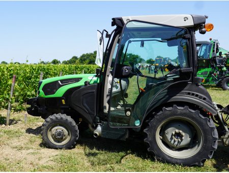
Engine configuration
Invented by Rudolph Diesel in 1897, the first diesel engine developed a power of 14.7 kW.It has evolved considerably since it was first presented at the 1900 Paris Universal Exhibition.
Engine characteristics
- Torque (Nm) is an engine's ability to withstand effort. The higher the torque value, the greater the engine's ability to withstand stress. This concept is important when working the soil.
- Torque reserve corresponds to an engine's ability to withstand a one-off increase in workload, without increasing engine speed or changing forward speed. It is expressed in %.
- The power (W) is the result of multiplying the torque by the engine speed. Technological developments in engines mean that maximum power can be obtained at an engine speed lower than the nominal (maximum) speed.
- Hourly consumption (l/h) is a variable value, since it depends on the engine's rotation speed and the load factor.
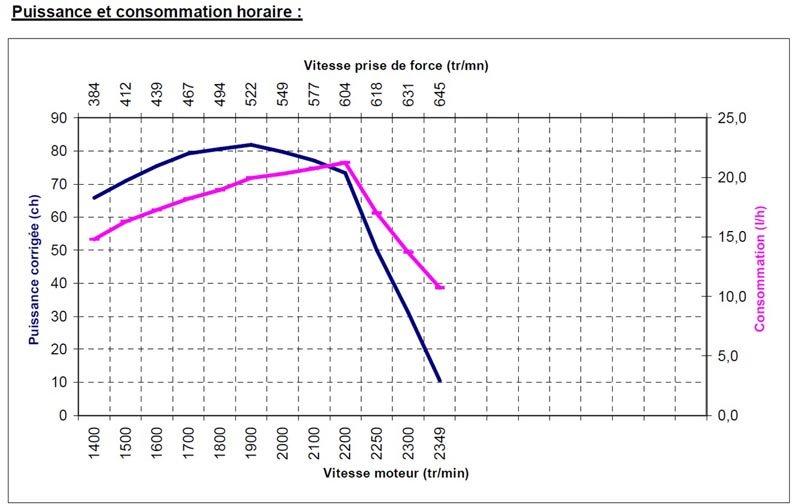
Power and hourly consumption - CUMA
- Specific consumption (g/kWh) corresponds to the mass of fuel required to produce 1 kW for one hour. This often misunderstood concept can be used, for example, to compare the hourly consumption of different engines of the same power. A fuel-efficient engine has a low specific consumption value.
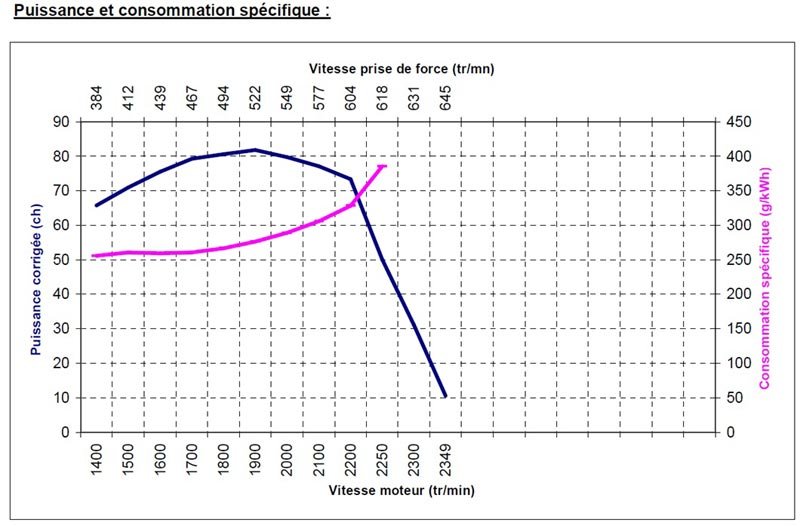
Power and specific consumption - CUMA
- Engine power standards.
- The SAE J1995, ISO TR 14396, EC 97/68 and 2000/25/EC standards are referred to as gross power standards. Depending on the standard used, power is measured using an engine without the various accessories, air filter, fan and exhaust silencer (SAE J 1995 corresponds to the American standard).
- The ECE R24, CEE 80/1269 and DIN 70020 standards give a net power value. Engine power measurements are more stringent than the previous standards. During measurements, the engine is fitted with the majority of accessories (fan, exhaust system, etc.). The ECE R24 standard corresponds to the European standard.
- The OECD standard corresponds to the power delivered at the power take-off.
As a result, engine manufacturers claim power levels that are difficult to compare from one manufacturer to another. For example, at Massey Fergusson, New Holland, Mc Cormick and John Deere, the advertised power is a gross power corresponding to the ISO TR 14396 standard. Other manufacturers use standards expressing net power, such as Same, Deutz and Fendt.
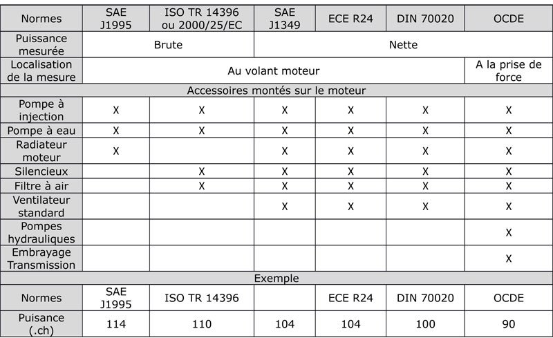
Table of engine power standards
All this information can be used to choose the right engine for the job in hand (ploughing, traction, etc.). For work requiring traction, a high engine torque will be needed to provide strong pulling power. New-generation engines offer high torque at a relatively low engine speed, so you can get plenty of pulling power without having to accelerate too much. This is known as starting torque. Today, maximum torque is generally obtained at 1500 rpm. This gives high pulling power at low revs. To meet regulatory requirements, engine manufacturers have developed certain engine components.
Injection system
In practice, there are two main types of diesel engine. They are classified according to whether they use direct or indirect injection.- Direct injection
- Indirect injection
- Common rail
Pollution control systems
In response to the development of mechanisation in agriculture, standards were introduced in the 1990s limiting CO2, NOx and fine particle emissions. They are not applied in the same way worldwide, with several countries or groups of countries issuing their own standards. The European Union has adopted a "Stage" system, which is very similar to the American "Tiers" system.Several technologies are being used to limit emissions, including high-pressure direct injection (common rail) and turbochargers. These developments are not enough to comply with Stage IIIB, which aims to significantly reduce NOx and fine particle emissions. Engine manufacturers have had to integrate new components such as EGR and SCR technology.
The technological solutions applied to standard tractors are not adapted to specialist tractors. In fact, specific tractors have to comply with maximum width constraints, making it difficult to integrate certain systems (EGR or SCR). A derogation has therefore been granted for manufacturers of low-power specialist tractors (between 49 and 74 bhp). They therefore have until 2017 to equip their specific models with engines that comply with the "Stage IV" standard.
- EGR (Exhaust Gas Recycling) technology
Incorporating exhaust gases into the air intake leads to imperfect combustion, producing fine particles. It is therefore necessary to capture them using a particulate filter. Once captured, they are destroyed by regeneration, which consists of burning the particles by raising the temperature in the filter. This phase is "natural" when the engine is running for a long period, or "forced" by the addition of extra fuel to the engine.
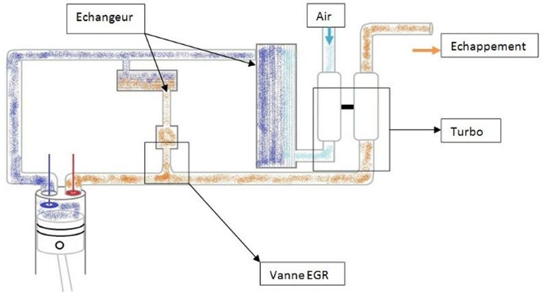
Diagram of how EGR technology works © AgroSup Dijon
- SCR (Selective Catalyst Reduction) technology

Schematic diagram of how SCR technology works © AgroSup Dijon
The diagram above shows the 5 stages in the pollution control process using SCR technology. These are as follows
- oxidation catalyst producing H2O
- injection of AdBlue required for the following reaction
- hydrolysis catalyst ensuring the formation of NH3 by reaction between the nitrogen and water molecules
- sCR catalyst converting Nox molecules into nitrogen molecules (N2) and water (H2O)
- the final oxidation catalyst, which converts the NH3 molecules produced previously into nitrogen (N2) and water (H2O).
Engine, gearbox and hydraulic oils
Engine oils
There are three types of oil:- Mineral oil: this is at the lower end of the value scale, derived directly from refined crude oil. It is rarely used today.
- Semi-synthetic oil: this is the middle of the range. It is made up of 35% synthetic oil and 65% mineral oil. It is recommended for low-efficiency engines.
- Synthetic oil: this is the highest performance oil. It is made up of a base and additives. This oil has good adhesion properties and is more resistant to ageing. Oil change intervals are increased.
The role of oil is to protect and cool moving parts. All oils comply with viscosity and quality standards. The most common standards are SAE and API.
SAE = Society of Automotive Engineers is an international organisation that tests and approves the viscosity of oils. A distinction is made between SAE "engine" and SAE "transmission" grades.
API = American Petroleum Institute is a standard classifying the different types of transmission oil.
Viscosity corresponds to the oil's resistance to flow as a function of temperature. As viscosity decreases with increasing temperature, the oil must both retain its role as a protective film and remain sufficiently fluid to circulate freely in the engine.
There are monograde and multigrade oils (which have a range of viscosity depending on temperature).
- Monograde oils are rarely or never used. They are intended for the lubrication of simple mechanics, such as old-generation engines.
- In the case of multigrade oils, polymer-based additives are added to the composition of the oil. This combination limits differences in viscosity when hot and when cold. As its name suggests, a multigrade oil has a cold grade and a hot grade. The cold grade is indicated by the first number (15W40). This refers to the oil's ability to lubricate the engine when it is not at temperature (cold engine). The second number corresponds to the viscosity of the oil when hot. In other words, the oil's ability to retain its properties at higher or lower temperatures.
Gearbox oils
They have an additional classification that takes into account the viscosity of the oil and its composition. Gearbox oils frequently used in agriculture correspond to the GL4 or GL5 classifications.Hydraulic oils
These fluids are made from an incompressible mineral base to which additives are added to optimise the fluid's physical properties. Their role is to transmit the energy produced by the pump to a receiver (cylinder, motor, etc.) while lubricating and cooling the components in the hydraulic circuit.They comply with the ISO/AFNOR standard using the basic classes HH, HL, HM, HV and HG, each with different possible grades. Each grade is identified by a number ranging from 15 to 220. The grade corresponds to a viscosity at a certain operating temperature.
Biodegradable hydraulic oils
Developed more than twenty years ago, rapeseed-based hydraulic fluids are a response to the risks of pollution in the event of hydraulic circuit component failure. Despite a higher purchase price than oil from petroleum products, these oils offer some interesting qualities:- Increased oil change intervals. Unsaturated fluids have an oil change interval of 2000 hours. Saturated fluids have a service life of around 6,000 hours.
- Lower energy consumption thanks to optimised lubricity.
- The first is based on Triglyceride (HETG) and is generally used for hydraulic circuits with a working pressure of less than 210 bar.
- The second is based on a synthetic ester (HEES) and is recommended for hydraulic circuits with a working pressure of less than 420 bar.
Operator station
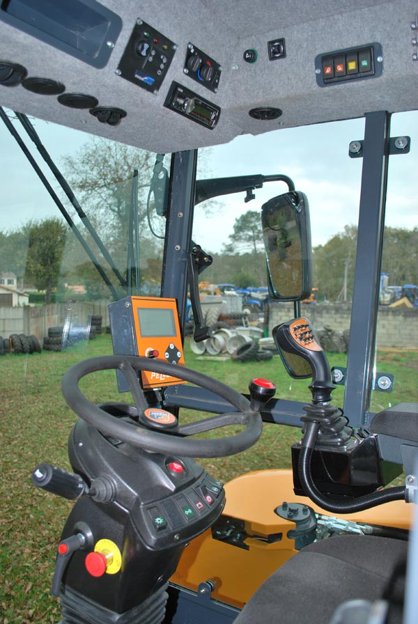
Driving position of a high-clearance tractor
The driving position has evolved considerably in recent years. It offers greater comfort thanks to the development of ergonomics. The seats are more comfortable thanks to the development of air suspension.
What's more, automatic driving aids are becoming increasingly common in high-power tractors. They are also appearing in some high-clearance tractor manufacturers.
Finally, operator protection is being optimised with the advent of more effective systems. When buying a tractor, it's important to clearly define the work to be carried out, so that you can choose exactly the components you need for the driver's cab.
Screen
This accessory is becoming an essential part of the driver's cab. Some standard tractor manufacturers offer a touch screen. It provides a wealth of information, helps with driving and facilitates the traceability of operations carried out in the field. Accessory suppliers offer screens that can be fitted to specialist tractors. This technology should be available as standard with the appearance of new-generation vineyard tractors (meeting Stage IV anti-pollution standards).Joystick or steering wheel
The development of on-board electronics has opened up many new possibilities. Controls are centralised on a joystick. This makes it possible to control the tractor's forward movement and hydraulic functions from a single control. The development of hydrostatic or continuously variable transmissions makes it easier to integrate additional functions on the joystick (management of implement lift and control of hydraulic spool valves).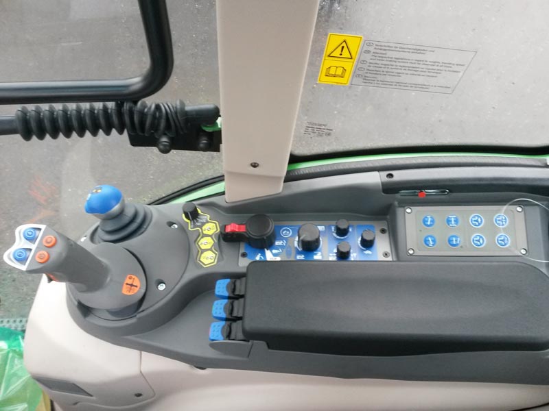
Joystick
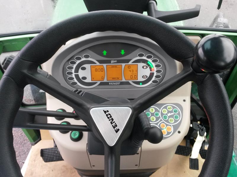
Steering wheel - Driving position
On-board electronics
Although this technology is widely used on standard tractors, it is struggling to make inroads on specialist tractors. Yet on-board electronics make it possible to approach driving in a different way. Whether it's a driving aid, with varying levels of performance depending on the technology used(optical sensor, ultrasound, GPS system, etc.). Or simply by providing information such as instantaneous fuel consumption, work rate/ha, or timed management of hydraulic spool valves.Filtration system
Designing the filtration system
Depending on the specific nature of the filtration system, the component parts differ from one system to another. To achieve maximum filtration, the system should be designed as follows:- A coarse particle pre-filter made of paper, glass wool or foam, placed upstream of the purification device. This protects against dust.
- A very high efficiency aerosol filter (type P3). Standard NF U O3-024-1 guarantees its performance.
- A class A activated carbon anti-gas filter, downstream of the aerosol filter, to compensate for any evaporation of the product retained by this filter.
Tightness and pressurisation
This is an important concept, as it limits the introduction of pollutants through openings not intended for ventilation. A cabin is difficult to seal because of the many cable passages. A classification can be used to determine different levels of filtration from 1 to 4.- Level 1: the cab offers no protection at all
- Level 2: Filtration protects the operator from dust
- Level 3: Filtration is higher than level 2, protecting the operator from aerosols
- Level 4: Filtration is higher than level 3, protecting the operator from gases
Maintenance
Regular maintenance is required to maintain the performance of the filtration system.- The dust filter must be cleaned regularly and replaced according to the manufacturer's recommendations.
- Activated carbon cartridges can be used in different ways. Either it is removed between each treatment, or it remains in place. The first solution avoids saturating the filter element too quickly. However, successive installation and removal can damage the seals, encourage preferential air flow and reduce filtration efficiency. When the cartridge is dismantled, it must be kept in airtight packaging, outside plant protection product storage areas, in accordance with the same rules as respirator cartridges. In the absence of more precise information from the manufacturer, the cartridge should be replaced every year.
To ensure optimum working comfort, the cab and its components must be kept in good condition. It is important to :
- frequently check the condition of door and window seals. Replace them when they no longer perform their function.
- maintain the air conditioning regularly, in accordance with the manufacturer's recommendations. Especially when it comes to servicing the evaporator and condenser. Checking the liquid charge, the oil level in the compressor and replacing the drier filter should be carried out by trained and equipped personnel.
Air conditioning
An essential part of any cab, air conditioning must be maintained to bring the cab interior up to temperature in just a few minutes. The temperature difference between inside and outside must be controllable. It is important not to direct cold draughts towards the driver, to protect his health.Transmission
Drivelines are constantly evolving. The first tractors were equipped with a rudimentary transmission with only three speeds and reverse. Gear changes required the tractor to come to a complete stop. The 1970s saw the introduction of synchronised gearboxes on agricultural tractors. This technological development simplified gear changes.Winegrowers' tractors generally have a mechanical gearbox offering (or not) the option of shifting certain gears under load. A second type of gearbox exists, the continuously variable transmission. Today, only one manufacturer (Fendt) offers this type of transmission on its specific tractor range.
Mechanical transmission
This technology equips the majority of vineyard and fruit-growing tractors on the market. Its role is to transmit the mechanical energy produced by the engine to the wheels. It is made up of various components, including the gearbox.There are several types of manual gearbox, the most commonly used today being the "parallel gear".
It consists of two shafts:
- The primary, which is linked to the engine crankshaft via the clutch
- The secondary, which carries the speed gears, idler gears, synchronisers, etc.
The components of this type of transmission differ from those of a 'mechanical' transmission. The reduction or multiplication of output shaft speeds is achieved by epicyclic gears mounted in cascade. Gear changes are controlled electrically by a computer. The whole system ensures perfect synchronisation of the many moving parts.
Continuously variable transmission
This technological development was first presented by Fendt tractors in 1996. It combines the efficiency of a power-shift transmission with the advantages of a hydrostatic transmission. It offers users an infinite number of ratios, with no loss of torque, to suit all applications.The continuously variable transmission combines the strengths of a hydrostatic transmission with those of a mechanical transmission. The former allows low forward speeds requiring little traction power. On the other hand, this transmission cannot withstand heavy loads and high speeds (for transport work, for example), because the hydraulic components are not designed to transmit high torques. Mechanical transmission has the advantage of overcoming the disadvantages of hydraulic transmission. So, by combining a hydraulic transmission with a mechanical transmission, continuously variable transmission combines the advantages of both technologies and delivers greater efficiency.
The continuously variable transmission consists of two main parts:
- a hydraulic part
- a second mechanical part
The hydraulic motor then drives a gearbox with two mechanical ranges (field speeds and road speeds), which transmits the torque to the wheels. This applies at low speeds, because as the speed increases, the motor's displacement decreases until it reaches zero, the pump's displacement being at its maximum to lock the epicyclic gear train's ring gear.
Hydrostatic transmission
This is an "automatic" transmission, since the system acts as both clutch and gearbox. Its operating principle is relatively simple. The internal combustion engine (or electric motor) generates rotary energy which drives a positive-displacement hydraulic pump. This pump transforms the mechanical energy (produced by the engine) into hydraulic energy, which drives the hydraulic motors.Tyres
Tyres provide the link between the tractor and the ground. There are two categories of tyre on the market: diagonal and radial structures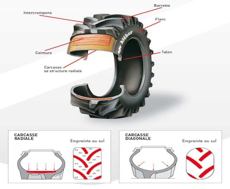
Tyre structures
- Diagonal tyres have a rounded shape. They are more suited to low-speed transport operations. As the tread is integral with the sidewall, this type of tyre offers good lateral stability. However, the load distribution is not optimal, so it is less suited to ploughing work.
- Radial structure tyres are more square in shape. Developed by Michelin in the 1970s, they are more versatile. The sidewalls and tread work independently. Load distribution is optimised, generating less settling.
Low-pressure tyres are frequently used in arable farming, and are becoming increasingly popular on grape harvesters and fruit tractors. This type of tyre has the particularity of having a large air volume, essentially thanks to a wider tread. This makes it possible to support heavy loads at moderate pressures, reducing ground pressure and therefore the risk of compaction and rutting.
The tracked undercarriage is another alternative that limits soil compaction. Manufacturers such as Track Equipement offer innovative technical solutions that can be adapted to a wide range of tractor models. The height of the tractor and its ground clearance remain the same, so there are no changes to the attachment of implements. Only flanges are added, but these can be easily removed. When the tracks are removed, the tractor returns to its original configuration.
As far as maintenance is concerned, according to the manufacturing principle, it simply involves cleaning and regular lubrication.
How do you read the marking on a tyre?
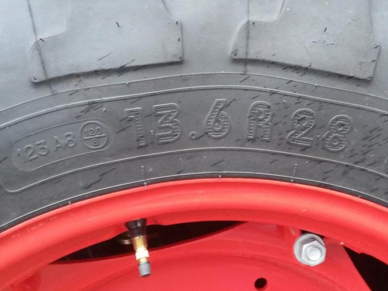
| 16.6 | Section width (in inches) |
| R | Radial tyre |
| 28 | Rim diameter (in inches) |
| SUPER VINE | Structure type |
| 123 | Load capacity index |
| A8 | Speed symbol |
Hydraulic system
An essential part of the agricultural tractor, the hydraulic circuit is increasingly used to perform a variety of functions, such as steering, braking, transmission and implement control.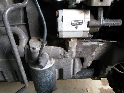
Hydraulic circuit: single pump
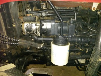
Hydraulic circuit: double pump
There are two types of hydraulic circuit, depending on the power of the tractor and its flow requirements (l/min).Tractor hydraulic circuit
Open centre" circuit
The "open centre" circuit is generally designed for low-power tractors. It consists of one (or more) hydraulic pump(s), often gear-driven. One pump is dedicated to the safety systems (steering, braking) and a second (the main pump) supplies the various implements or accessories. The flow of oil circulates continuously through the spool valves, whether they are in use or not. The flow rate is regulated according to the pressure exerted on the spool valve. The maximum flow rate is often less than 110 l/min and is dependent on engine speed. This technology is inexpensive, but energy-consuming, since the flow of oil is constantly circulating in the spool valves (oil overheating).Some manufacturers offer a slightly more efficient technology: the "load-sensing open centre" circuit. It differs from the "open centre" circuit in that a pressure limiter is installed between the pump and the spool valves. When the spool valves are not activated, the oil is returned directly to the tank without passing through the spool valves. This reduces energy losses.
Closed centre circuit
The "closed centre" circuit is used for high flow rates (over 110 l/min). Today, only Fendt offers this technology on specialist low-power tractors. This circuit consists of a variable displacement pump, which supplies the spool valves only when they are activated. The pump's displacement adapts according to hydraulic requirements, so its flow is independent of engine speed.A load detection system is often coupled to the closed centre circuit. This is known as load-sensing technology. The pump flow is then regulated according to the pressure in the hydraulic circuit. This technical solution goes hand in hand with the development of on-board electronics on tractors, enabling repetitive functions to be automated. In this way, it is possible to set the flow rate and operating time of a spool valve according to the needs of use.
Experiment
See the list of experimentsSee more - Fuel consumption and tillage in organic viticulture - 2020
- [EQUIPMENT TEST] Case IH Quantum 95F tractor - 2016
- [EQUIPMENT TEST] Fendt 210P Vario tractor - 2016
- [EQUIPMENT TEST] Class Nexos 240F tractor - 2016
- [EQUIPMENT TEST] Tractor Kubota M 9540 - 2016
- [EQUIPMENT TEST] Lamborghini RS 100 tractor - 2016
- [EQUIPMENT TEST] Lindner Lintrac 90 tractor - 2016
- [EQUIPMENT TEST] Tractor Landini REX 100 GT - 2016
- [EQUIPMENT TEST] Massey Fergusson 3660F Tractor - 2016
- [EQUIPMENT TEST] Comparative test bench, ten vineyard tractors - 2016
- [EQUIPMENT TEST] Tractor New Holland T4.95F - 2016
- [EQUIPMENT TEST] Tractor Same Frutteto 3S 110 - 2016
- Fuel consumption in the vineyard - 2015
- Tractor driving simulator - 2014
- [EQUIPMENT TEST] Drago high-clearance crawler tractor - 2014
- [EQUIPMENT TEST] Frema high-clearance tractor - 2014
