Sprayer
Spraying consists of spreading a liquid in the form of droplets on the vine. The size of the droplets varies according to the work objectives and the surrounding conditions. The smaller the droplet size, the greater the coverage. The risk of droplet drift and/or evaporation also increases with droplet fineness.
Vineyard sprayers are made up of several essential components, such as the tank, pump and nozzles, and can be mounted, semi-mounted or trailed. Pressure regulation and filtration are crucial for effective spraying, while the pumps and ventilation systems play a key role in the uniform distribution of the spray liquid.
Precise adjustment at the start of the season and good maintenance of the sprayer are essential for satisfactory spray quality.

What is spraying?
Spraying consists of spreading a liquid in the form of droplets, the size of which is adapted to the work objectives. The smaller the droplet size, the greater the coverage. The risk of droplet drift and/or evaporation also increases with droplet fineness.
Vineyard spraying differs greatly from field crop spraying, partly because of the diversity of vineyard management methods, but also because of the different objectives of the work to be carried out. The main tasks are
Vineyard spraying differs greatly from field crop spraying, partly because of the diversity of vineyard management methods, but also because of the different objectives of the work to be carried out. The main tasks are
- Treatments to cover all the foliage
- Localised treatments on the fruit-bearing zone
Spraying technologies
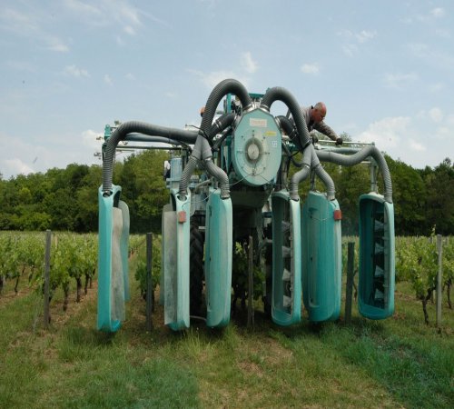
There are three main spraying technologies used in viticulture:- spray projection (mainly used for weed control)
- overhead spraying
- pneumatic spraying
The different types of sprayer have many features in common.
In chronological order of progress of the liquid in the sprayer, we find :
In chronological order of progress of the liquid in the sprayer, we find :
- The tank
- The filter (suction)
- The pump
- The regulator
- Distributor(s)
- Boom sections
- Filter(s)
- Nozzles or pellets
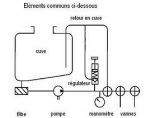
Common elements for spraying
Components of a sprayer
Chassis, coupling system, tank and axle
The chassis
Generally of welded design, the chassis of a vineyard sprayer is made up of a "U" or "tube" section. The U-section offers a number of advantages, in particular resistance to corrosionWhen the frame is made up of a "tube" section, it is important to ensure that the ends of the frame are sealed to prevent internal corrosion.
The coupling system
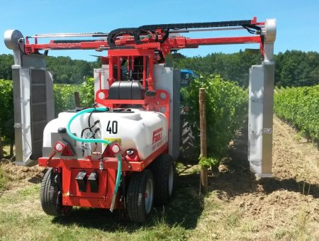
There are 3 main types of carriage:- Porté
Mounted sprayer (on the 3-point) - Nicolas
- Semi worn
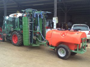 Semi-mounted sprayer (3-point + hitch) - Clemens
- Trailed
Trailed sprayer (hitch) - Nicolas
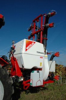
The tanks
- The main tank (or barrel) is the spray liquid reservoir.
- The rinsing tank contains the clear water needed to clean the circuits and dilute the tank contents, and must be at least 10% of the volume of the main tank.
- Finally, there is a third tank for rinsing hands and/or nozzles.
They are generally made of polyethylene or laminated polyester , but you can also find 'home-made' tanks in stainless steel, mainly on high-clearance tractors when you're looking for a 'made-to-measure' solution.
| Materials | Benefits | Limits |
|---|---|---|
| polyethylene | ▪ Easy to clean ▪ Resistant |
▪ Difficult to repair |
| laminated polyester | ▪ Easy to repair | ▪ Rough interior makes cleaning more difficult ▪ Sensitive to shocks and vibrations |
NOTE:
Tanks generally have a capacity of between 300 and 2000 litres.
When talking about tank volume, a distinction must be made between nominal, total, dilutable residual and total residual volume.
Nominal tank volume = maximum tank capacity.
Total tank volume = nominal volume + 5% volume (safety)
Dilutable residual volume = volume of liquid remaining in the bottom of the tank after the pump has been de-primed + in the tank return circuit + in the compensated returns + in the filters + in the agitation system + in the pipes of any product incorporation tank.
Total residual volume = dilutable residual volume + volume of spray liquid remaining in the pipes from the tank to the diffusers.
The axle
There are three types of axle on the market:- Single axle
- Double axle
- Bogie axle
The choice of axle type is based on a number of objectives:
- volume to be loaded
- stability required during treatments
- limiting soil compaction.
Double or bogie axles offer good stability during spraying operations, limiting pressure on the ground and, consequently, soil compaction. On the other hand, they have the disadvantage of reducing the turning radius.
The pump
In a way, it's the heart of the sprayer. The pump moves the liquid not only for spraying but also for agitation in the tank. It is characterised by a characteristic curve that represents the pump's ability to move the spray liquid as a function of the required pressure.There are several pump families on the market:
- Centrifugal pumps
These pumps are relatively simple in design. They have the distinctive feature of delivering high flow rates at low operating pressures. This type of pump is non-volumetric and tends to deflate easily.
How a centrifugal pump works:
The liquid is drawn in at the impeller shaft. The liquid flows through the impeller at high speed. The centrifugal force sends the liquid towards the discharge, causing it to acquire kinetic energy, which is converted into pressure.
- Piston pumps
Piston pumps are used on many sprayers because they offer a wide range of working pressures. However, the complexity of design and the cost (purchase and maintenance) mean that these pumps are being abandoned in favour of piston-diaphragm pumps.
How a piston pump works:
The piston moves in a straight line with a reciprocating motion to pressurise the liquid. A suction valve and a delivery valve allow the liquid to enter and leave the pump. To regulate the flow, the pump is fitted with an air bell to smooth out the pressure (clipping low and high pressures).
- Piston diaphragm pumps
These are the most common type of pump, as their design limits maintenance costs since the liquid is no longer in contact with the pump's component parts. However, these pumps do require regular maintenance (checking diaphragms, valves and oil level).
How a piston-diaphragm pump works:
The piston is framed by two diaphragms. The reciprocating movement of this piston is in phase with the suction or discharge diaphragms. A suction valve and a discharge valve allow the spray liquid to enter and exit the pump. Like piston pumps, they are generally combined with an air bell.
The air bell
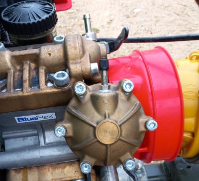
Air bell
This accessory is fitted to piston or piston-diaphragm pumps. It limits pulsation in the discharge circuits. The air bell is essential on piston-diaphragm pumps.
The internal pressure of the air bell is determined according to the working pressure.
Generally, it varies between ½ (for "low" pressures) and 1/3 (for "high" pressures) of the working pressure.
The internal pressure of the air bell is determined according to the working pressure.
Generally, it varies between ½ (for "low" pressures) and 1/3 (for "high" pressures) of the working pressure.
Filters
The filtration system must comprise several filters:
- the sieve : located at the manhole, this retains coarse elements such as lumps formed when the spray liquid is poorly prepared
- the pump suction filter: located between the tank and the pump
- the pump delivery filter (optional): located between the pump and the control system.
- section filters: located after the section cut-off valves and diffusers
- nozzle filters: positioned last, just before the pneumatic diffusers or nozzles.
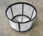
Sprayer filling sieve
The fineness of filtration is indicated by the mesh count, which corresponds to the number of wires per inch (1 inch = 25.4 mm). The higher the number, the greater the filtration.
Indication of filter fineness:
- intake filter: 32 to 50 mesh
- section filter: 50 to 80 mesh
- nozzle filter: 80 to 100 mesh
As a reminder:
The filtration capacity of the last filtration levels must be adapted according to the risk of clogging the nozzles and the recommendations given by the suppliers.
It is possible to adjust the filtration fineness but also the volume of the filtration bowl if the filters become clogged.
There is an international colour code (generally respected) for determining the filter's filtration capacity (see opposite)
- intake filter: 32 to 50 mesh
- section filter: 50 to 80 mesh
- nozzle filter: 80 to 100 mesh
As a reminder:
The filtration capacity of the last filtration levels must be adapted according to the risk of clogging the nozzles and the recommendations given by the suppliers.
It is possible to adjust the filtration fineness but also the volume of the filtration bowl if the filters become clogged.
- Filtration that is too loose can lead to clogged nozzles.
- Filtration that is too tight can lead to clogged filters.
There is an international colour code (generally respected) for determining the filter's filtration capacity (see opposite)
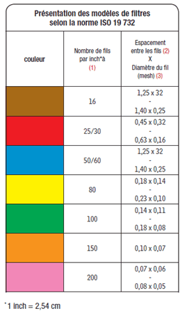
MESH correspondence table
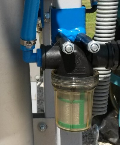
- Some suppliers offer filters with a transparent bowl. This is particularly useful for checking the cleanliness of the filter without having to dismantle it.
Regulation
The regulator
This is an essential part of the sprayer, as it regulates the working pressure. It causes a greater or lesser proportion of the pump's flow to return to the tank, to ensure a regular flow to the boom.
TANK RETURN FLOW = PUMP FLOW - BOOM FLOW
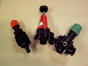
Spray regulators
- Constant pressure regulation
- Calibrated return flow regulation (also known as DPM: flow proportional to engine speed).
The major advantage of this type of regulation is that the flow rate is virtually proportional to the forward speed at a given gear and within a range of 150 revs of PTO speed (450 to 600 rpm).
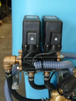
DPAE
" Electronic Flow ProportionaltoForwardSpeed": these systems regulate the flow rate according to the forward speed in order to maintain the same volume/ha. these are consoles connected to a pressure sensor and/or flow meter and a speed sensor (GPS or sensor positioned on the wheel). The system regulates the pressure according to the volume/ha chosen in relation to the tractor's forward speed, once the working width has been set in the system. These consoles can also be used to control the opening/closing of sections, and to display and adjust the various spraying parameters (flow rate, pressure, volume/ha, etc.). Beware, some of the parameters displayed on the console are sometimes (often) calculated and not measured, giving the user the illusion of precision/reactivity that they cannot achieve!Distributors or valves
These are known as "valves".
A sprayer is generally equipped with a general cut-off valve and valves for each boom section.
For safety reasons (no spray liquid in the cab), manually-operated spool valves are not permitted in closed cabs. They are replaced by solenoid valves or motorised valves. Motorised valves are preferred to solenoid valves for reasons of reliability and maintenance, although solenoid valves have the advantage of closing almost instantaneously.
A motorised valve can take up to 1 second to close. Both closing devices must be adapted to the operating pressures in the circuit, otherwise they will deteriorate rapidly. Adjustable compensated-return valves maintain a stable pressure when closing a section of manifold.
Sprayer dispensers

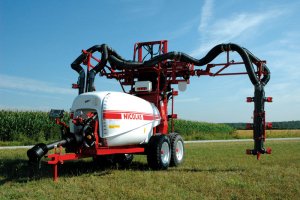
Ramps
They support the nozzle holders or diffusers, the number of which varies according to the appliance. Their configuration is very different depending on the type of equipment.Nozzle holders
Supporting the nozzle or the pellet, they generally include anti-drip devices that stop spraying when a valve is closed.The opening pressure of the anti-drip devices is around 0.3 to 0.8 bar.

Ramp and nozzle holder
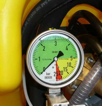
Pressure gauge
The pressure gauge is a key element on a sprayer, just as the speedometer is essential not only for setting up the sprayer, but also for monitoring it during work. The pressure gauge indicates the pressure at the point where it is installed. This pressure may be different at the nozzles depending on the pressure drops in the circuit (length and diameter of supply pipes, presence of obstacles to flow such as elbows, drip stops, pipe obstructions, etc.).

Digital pressure gauge
Two types of pressure gauges are used:
- The needle manometer (Bourdon tube) uses the deformation of a bent brass tube to move the needle and indicate the pressure on a dial.
- The electronic manometer, which uses a strain gauge for measurement and a digital display.
For sprayers fitted with a digital pressure gauge, it is recommended to add a needle pressure gauge to check the information given and detect a problem more easily.
Needle pressure gauge
The manometer must be adapted to the pressures to be measured, but a safety margin is essential to avoid the devastating effects of false manoeuvres that damage the brass tube (exceeding the elasticity limit).
Expanded scale pressure gauges give good accuracy at low pressures, with a reading over 2/3 of the needle's travel. The last third allows high pressures to be reached with poor accuracy, but protects the mechanism.
Needle pressure gauges are not allowed in the cab, but they can be placed outside the cab, behind the cab window and within sight of the driver.
- Shown here is a pressure gauge with an accuracy of 0 to 5 bar, ideal for pneumatic sprayers.
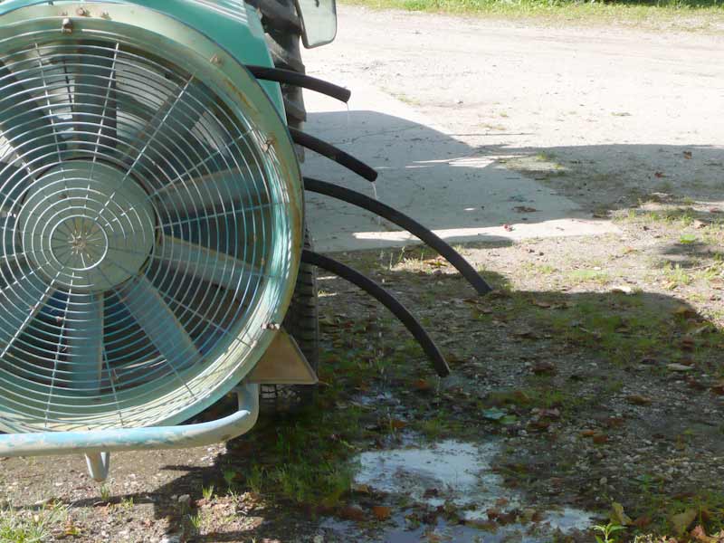
Ventilation
Air flow is a very important parameter for successful spraying. It can be generated by one or more fans, depending on the sprayer model.In the case of pneumatic sprayers, the air speed breaks up the liquid (spray mixture) into droplets and also plays a role in mixing the leaves and penetrating the product into the vegetation.
For air-blast sprayers, the main function of the air flow is to carry the droplets towards the vegetation, stirring it so that the spray mixture is evenly distributed throughout the canopy.
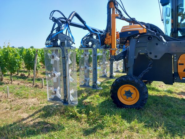
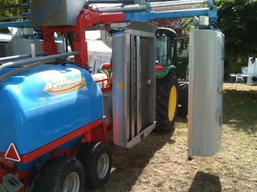
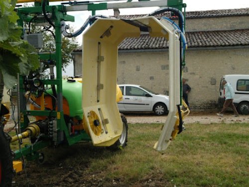
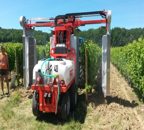
Recovery panels
Historically used for winter treatments with sodium arsenite, sprayers with recovery panels had, since the ban on this product in November 2001, returned to the obscurity of sheds. However, new environmental concerns and the ECOPHYTO plan have given them a second lease of life. While the first machines designed for winter spraying were simple in design (generally a single panel spray), the use to which they are now put (spraying throughout the season) has seen them evolve considerably, in particular with the addition of a blower. Most of them are mounted on a carrier jet (a droplet production method more suited to recovery), although there is some pneumatic equipment fitted with panels. There are various systems for recovering the spray liquid from the bottom of the panels. These generally involve a dedicated piston pump, but peristaltic pumps and hydro-injectors are not uncommon. While they can save around 30% of spray mixture over an entire campaign, they have a number of drawbacks (cost, space requirements, work rate, etc.) which have considerably limited their use. The Cognac vineyards (wide vines, moderate slopes) have by far the highest proportion of sprayers fitted with panels.
Bertoni sprayer (Arcobaleno) - Photo credit IFV (Davy)
Dagnaud sprayer (Turbipano) - Photo credit IFV (Davy)
Friuli sprayer (Recovery) - Photo credit IFV (Davy
Dhugues sprayer (mounted on high-clearance tractor for vines at 1.5 m) - Photo credit IFV (Davy)
Settings and uses
There is no standard setting, because every sprayer is different, and the spraying constants are also different depending on the tractor used, the objectives and the spraying constraints.
Formula for adjusting the volume of spray liquid/ha
Here is the formula for calculating the volume of spray mixture applied per hectare
Q (L/ha) = 600 x D (L/min)
V (km/h) x L (m)
V (km/h) x L (m)
- Q: quantity of spray liquid to be applied in litres per hectare (L/ha)
- D: total sprayer output in litres per minute (L/min)
- V: forward speed in km/hour
- W: working width in metres (the distance between 2 passes of the tractor)
Demonstration by example:
Number of rows treated per pass: 4 full rows with a row spacing of 2 metres. So L = 8 m
Total output of sprayer nozzles: 12 L/min
Working speed: 5 km/h.
The volume of spray mixture sprayed per hectare will be :
Vol (L/ha) = (600 x 12) / (5 x 8) = 180 L/ha
Total output of sprayer nozzles: 12 L/min
Working speed: 5 km/h.
The volume of spray mixture sprayed per hectare will be :
Vol (L/ha) = (600 x 12) / (5 x 8) = 180 L/ha
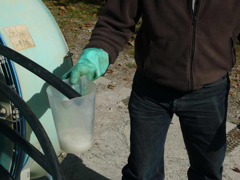
Flow measurement at nozzles
This method is preferable where it can be carried out (with the ventilation switched off) because, although it takes longer, it can detect differences in flow rates between the various nozzles or diffusers. Simple to carry out, all you need is a test tube and a stopwatch, then measure the volume of liquid flowing from each nozzle (or diffuser) for one minute.
- But there's no need for a test tube or stopwatch - the digital flow meter gives a direct reading of the flow from each nozzle in just a few seconds!
Total flow measurement
If the sprayer's ventilation cannot be disengaged (mechanical problem), the above-mentioned calculation method will be difficult to apply. In this case, another (less precise) method can be used:
- Fill the spray tank to the brim after checking that the entire supply circuit is full and free of air up to the nozzle outlet.
- Run the sprayer for 5 minutes.
- Fill the sprayer with a graduated container so as to fill it to the brim again.
By dividing the amount of water you added to refill the tank by 5, you will know the total flow rate (D) of your sprayer. However, you won't know whether the flow rates from the nozzles or diffusers are uniform or not.
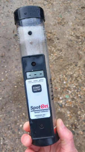
Spot On digital flow meter
Other methods or tips for measuring nozzle or diffuser flow rates :

Spray constants settings
To optimise sprayer settings, a number of parameters need to be taken into account. Here are the main ones:
- tractorpower take-off (PTO)speed -> check with a tachometer
- determining a desired forward speed. To do this, you need to combine a gearbox ratio and the PTO speed, which is generally set at 540 rpm (except for vario engines, which use the same method). Generally speaking, spray quality tends to deteriorate with increasing forward speed. The choice of speed therefore results from a compromise between work rate and quality of application, generally between 5 and 7 km/h.
- the technology used: pneumatic, air blast, etc.
- the volume of air displaced (the higher the volume, the less impact the increase in forward speed will have)
- the distance between the diffuser and the foliage
- the condition of the soil in the plots being treated (uneven soil -> risk of the boom swinging)
When adjusting equipment fitted with mixed devices (e.g. hands and guns), you need to ask yourself "who does what?
In other words, you need to know which part of the foliage will be treated by which element. This kind of thinking can lead to different choices of nozzles depending on the height of foliage treated by the nozzles, or the number of nozzles needed to treat the same height of foliage.
Preferential spray circuit
What is a preferential circuit?
This is a hydraulic circuit that will offer less resistance than another and on which the flow of liquid will be directed. It induces a heterogeneity of flows between the diffusers or the fingers of the same diffuser.
What causes a circuit to have preferential fluid flow?
- une hauteur de refoulement différente.
- des pertes de charge différentes (longueur de circuit, diamètre de tuyauterie, présence de coude ou écrasement du tuyau)
Il n'y a aucune vidéo à afficher.
Technical and economic selection criteria
When it comes to spraying, we can talk about targets that need to be reached. Appropriate means must be used to reach them while respecting their environment.
Clearly, the success of a treatment is the result of a synergy between knowledge of the disease or pest, control methods and a good application technique.
Clearly, the success of a treatment is the result of a synergy between knowledge of the disease or pest, control methods and a good application technique.
Selection criteria
Adaptation to traction equipment
- power available from the PTO
- tractor balance for mounted sprayers
- oil flow available if required
Vineyard configuration
- planting width
- height of foliage
- foliage thickness
- topography (slope and/or incline)
Simplicity of equipment and site throughput
Particular points to watch out for
Tank gauge :
A dry gauge (no contact with the spray liquid) will remain legible from a distance after several years. Visibility from the cab is obviously a plus.
Rinsing tank:
Legally, it must have a capacity greater than or equal to 10% of the volume of the main tank.
Hand-wash tank :
Mandatory presence and good accessibility.
Pressure gauge:
Must be accurate and adapted to the working pressure. Positioned so as to be easily seen by the tractor driver.
Drip guards:
Mandatory for CAP regulations.
Filters :
Number and ease of cleaning, compliance with filtration graduation.
Diffuser adjustment:
Being able to give them a vertical angle (inclination) and/or a horizontal angle (orientation) is often an important point for improving plant coverage.
Safety and technical control
Machine design: operator safety
Before a sprayer can be placed on the market, it must meet a number of technical requirements that comply with Machinery Directive 2006/42/EC, which came into force in January 2010.
The design rules set out in this directive are designed to meet operator safety requirements.
This directive lays down the design and construction rules to meet the essential health and safety requirements for the operator. This Machinery Directive (2006/42/EC) will be replaced by Machinery Regulation 2023 (1230), which was published on 29 June 2023 but will not come into force until 20 January 2027.
Machine design: environment
Sprayers must also comply with Directive 2009/127/EC (Amendment to the Machinery Directive which imposes environmental requirements on new sprayers in addition to the safety requirements as defined in the Machinery Directive 2006/42/EC)
The main requirements are
The main requirements are
- Accuracy of application and prevention of drift
- Ease of maintenance and cleaning
- Easy connection of measuring devices such as pressure sensors and flow meters (particularly for technical inspections)
Technical inspection of sprayers
Checks on agricultural sprayers have been compulsory in France since 1 January 2009. The inspection is periodic and must be repeated every 3 years.
During the technical inspection of the sprayer, a number of points are checked, including
During the technical inspection of the sprayer, a number of points are checked, including
- The general condition of the equipment
- The presence of safety devices
- The condition of the plugs and the operation of the filling and emptying systems, etc
- Condition of pipes, hoses, circuits, etc
- Proper operation of measuring instruments: pressure gauges, etc
- Condition of filters
- Flow rates of nozzles, pellets, etc
The list is not exhaustive.
Reminder of regulations concerning ZNT, DSR, DVP and buffer strips
New technologies & spraying
Although still underdeveloped in the field of spraying, new technologies are appearing timidly to facilitate the work of treatment and / or traceability. These are usually sensors/actuators coupled to a GPS. They can be used to modulate the dose on an intra-parcel scale and/or automatically cut off sections at the end of the row (which is particularly useful in the case of narrow vines where the rows are not all the same length).
PWM nozzles can provide new technical solutions to take precision spraying a step further
.
Finally, traceability tools have also appeared to try and automate and simplify the recording of agricultural work and spraying in particular.
Other tools have also been developed to provide easy access to past and/or forecast weather data (weather stations, spatial data, etc.). They are often combined with models or Decision Support Tools
(https://decitrait.vignevin-epicure.com/login) to help the winegrower/advisor position treatments more effectively and choose the right product dose. Some allow simplified traceability of treatment operations.
Fluorescent spray quality control
One project, funded by the New Aquitaine Region, has been to develop a tool for assessing the quality of spraying. It was carried out by the Gironde Chamber of Agriculture, the CTIFL and theIFV as part of the Eval'Pulvé project .
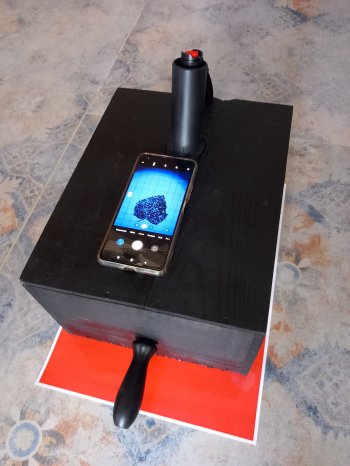
Box with UV light + smartphone

Visualisation of impacts on sheet
How it works
the tool consists of a case equipped with UV lighting. The smartphone is grafted onto this to read and take images.
- The vines are sprayed with a fluorescent tracer supplied by our partner Jean-Louis Talon, which fluoresces even when dry.
- Images are acquired in the field during the day. Thanks to the smartphone and the camera, there's no need to wait until sunset to see the results on the foliage.
Image analysis and interpretation
Image analysis processing enables the following measurements to be made:
- The number of impacts per cm ²
- An estimate of the median drop size (vmd)
- An estimate of the coverage rate on the leaf and the volume/ha
The data is processed retrospectively by computer.
The final objective is to develop an application enabling the user to self-assess the quality of application and to provide recommendations on settings.
Experiment
See the list of experimentsSee more - Choice of spraying techniques for winegrowing, the PERFORMANCE PULVE tool - 2022
- Vititunnel, an automatic system for covering vines to combat mildew - 2021
- Checking spray quality tutorial - 2020
- [EQUIPMENT TEST] Adjustment sheet: water-sensitive paper, how does it work? - 2020
- [EQUIPMENT TEST] Set-up sheet: black plates, how does it work? - 2020
- Order of introduction of plant protection products when mixing - 2020
- Sprayer wintering procedure summary sheet - 2019
- The 10 golden rules of vineyard protection - 2019
- PulvEco, a new online tool to assess the quality of spraying on wide vines - 2019
- How to optimise the use of recovery panel sprayers? - 2018
- Powder assessment - 2017
- Order of 4 May 2017, Placing on the market and use of plant protection products - 2017
- Evaluation of the effectiveness of drift nets - 2017
- Practical guide to setting up and using vineyard sprayers - 2017
- Optimising sprayer performance - 2016
- Checking spray quality tutorial - 2016
- Sprayer settings and equipment selection conference - 2016
- The benefits of supporting winegrowers in adjusting their sprayers - 2015
- Test results for recovery panels - 2014
- [EQUIPMENT TEST] Comparative test bench, sprayers with recovery panels - 2013
- Optipulvé: a tool for optimising application rates in narrow vineyards - 2013
- Direct injection of plant protection products in vineyards - 2011
- Checking your sprayer - 2011
- [EQUIPMENT TEST] Comparative test bench, drift reduction in viticulture - 2011
- [EQUIPMENT TEST] Comparative test bench, spraying wide vines - 2011
- Technical meetings on crop protection spraying - 2010
- [EQUIPMENT TEST] Comparative test bench, spraying wide vines - 2009
- All you need to know about storing plant protection products - 2008
- Which equipment for confined spraying - 2008
- Preparing sprays and managing phytosanitary effluents - 2007
- How can we improve spraying? - 2003